It is our goal at DIECASTING-MOULD.COM to provide our customers with the most satisfying die casting experience that is humanly possibility. All aspects of designing for die casting manufacturing are covered in this comprehensive guide that we have just published.

Various Methods of Die Casting
There are two primary methods of die casting, which are:HPDC stands for high pressure die casting, and LPDC stands for low pressure die casting. The HPDC system offers more precise details and tolerances. The mold is filled with molten metal that is injected into it at a high velocity and pressure. Although LPDC makes use of gravity to fill molds, the tolerances of the parts it produces are more relaxed. The Selection of MaterialsExamples of alloys that are frequently used for die casting include aluminum, magnesium, zinc, and tin-based alloys. Every one of them has distinctive qualities that should be taken into consideration
Aluminum (Al)Lightweight, resistant to corrosion, and machinable featureszinc (Zn)Excellent durability, meticulous attention to detail, and self-lubricatingMagnesizationflammable, machinable, and the lightest structural metal availableConsiderations in Draft FormThe draught, also known as the taper, makes it possible for parts to be easily removed from the die. Standard draft angles can range anywhere from one to three degrees, depending on factors such as the depth of a part, the thickness of its walls, and other factors. When compared to external surfaces, internal features typically require a draft angle that is twice as large.

Specifications for Wall Thickness
Fluid metal flow is encouraged by thin walls, but strength is compromised as a result. Colder temperatures and residual stresses are both increased by thick walls. The wall thickness of zinc die castings typically ranges from 0.381 to 0.889 millimeters, while the thickness of aluminum die castings typically ranges from 0.787 to 3.543 millimeters. Both Bosses and RibsWithout adding any additional material, these reinforcements make the structure more rigid. Create them with a minimum thickness of one millimeter, which is equivalent to 1.5 times the thickness of the surrounding area. Fillets and RadiiSmooth transitional fillets measuring 0.75 to 2 millimeters and radii at corners are used to prevent defects. Steer clear of acute angles of 90 degrees.
Concerns Regarding the Flow
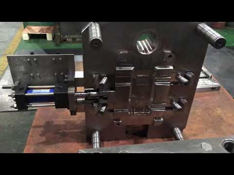
Vents, overflows, and wells should be strategically placed in order to vent air and ensure that the metal flow is optimized to fill all of the details. Design with a Parting LineFind the parting line, which is the division between the two halves of the die, in a place that is not easily noticeable in order to conceal any minor inconsistencies that may occur along it. The use of threads and undercutsWhen it comes to precision threading, alternative fabrication methods such as tapping or insert molding should be considered.
Undercuts necessitate the use of slides or cores, which add the complexity.
Placement of the Core Pins and the Ejector
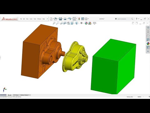
Plan the locations of the ejector and core pins while avoiding finished surfaces and edges in order to reduce the number of artifact defects. An Analysis of the Draft SimulationUtilizing mold flow simulation software such as Moldex3D, it is possible to virtually optimize designs prior to tooling in order to identify and address filling or ejection issues effectively.
Elements That Cause Embrittlement
Check for elements that cause embrittlement, such as iron, nickel, and silicon. In addition to increasing the hardness of alloys, their presence also decreases their impact strength. Account for Post-Making AllowanceIn order to finish intricate details and smooth surfaces, you should take into account a machining tolerance of 0.010–0.030 inches. Inserts as well as FastenersIf the properties of the alloy do not meet the functional requirements or the fastener interface, the design should employ metal inserts such as threads. Part Marking and Identification Include size markings and the company logo in a discrete manner without compromising the material's aesthetics or its functionality. Hopefully, this comprehensive guide on die casting design considerations and guidelines will assist you in achieving the best possible results from your casting endeavors. Give us a call if you have any further inquiries!